Scan Insertion is the design methodology in which the normal flop is converted into scan flop and stitched together into a Scan Chain.
Scan Insertion is the idea of adding some extra logic/structure to the design to improve the controllability and observability, inorder to improve testability of the design.
Extra logic is nothing but a 2 × 1 MUX is added to the normal flop.
What is scan insertion? Why we need scan insertion?
Scan insertion is the idea of converting normal flip-flop into scanned flip-flop by adding some extra logic and stitch them together to form a scan chain. Here, extra logic is nothing but a 2X1 MUX.
Scan insertion will provide controllability and observability over the design, so that the testability of the design is improved.
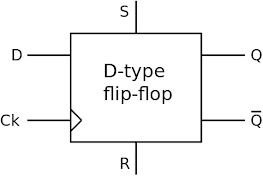
Normal D Flop

Scan Flop
Scan Chain: Set of scan cells stitched together.
Scan Group: Set of scan chains working parallelly form a scan group.
Scan Types:
- Full Scan -
- All the flops in the design are converted into scan flops.
- Partial Scan -
- Only some flops in the design are converted into scan flops (design requirement).

Scan Cell Working Principle:
- If SE is 0, then Functional Mode will work (input is D).
- If SE is 1, then Test Mode will work (input is SI).
- Shift phase = Q to SI path
- Capture phase = Q to D path
- Setup
- Analysis
- Insertion
Scan Chain Length:
Number of scan flops in the scan chain is considered as scan chain length.
Scan Chain Operation:
- Scan-In
- Capture
- Scan-Out

Shift Phase:
During the "Shift" phase, test patterns are loaded serially into the scan chain. Each test pattern bit is shifted through the scan chain and loaded into the flip-flops. The purpose of this phase is to set the initial values of the flip-flops to the desired test pattern.
The steps involved in the "Shift" phase are as follows:
- Set the scan enable signal to high.
- Apply a clock signal to the scan chain.
- Serially shift in the test pattern bits one by one.
- After all test pattern bits have been shifted in, disable the scan enable signal.
Capture Phase:
After shifting in the test patterns, the "Capture" phase captures the outputs of the combo logic to flip-flops to observe the responses. The purpose of this phase is to compare the captured responses to expected values and detect any faults.
The steps involved in the "Capture" phase are as follows:
- Set the scan enable signal to low.
- Apply a clock signal to the scan chain.
- Response is captured in next flop.

Patterns to Load: (1) 1 0 1
(2) 1 1 0


No comments:
Post a Comment